
Create a Small Game from Scratch Series: Endless Standing First-Person Shooter
Level: Beginner
Type: Blueprint
Version: 5.6
Download Project
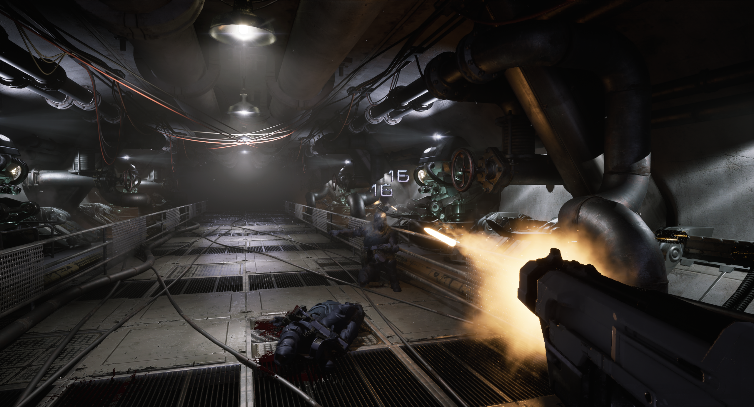
In previoius tutorial we have implemented blood splatters and we can finally work on the level for Shooter Tutorial.
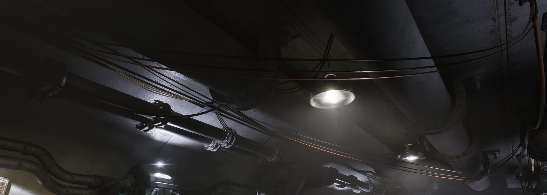
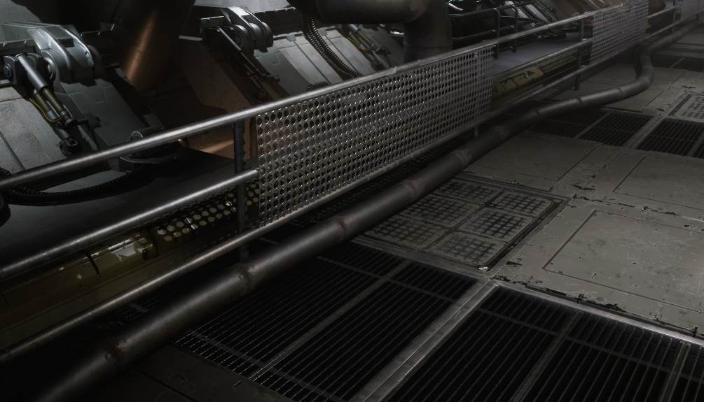
Final Result
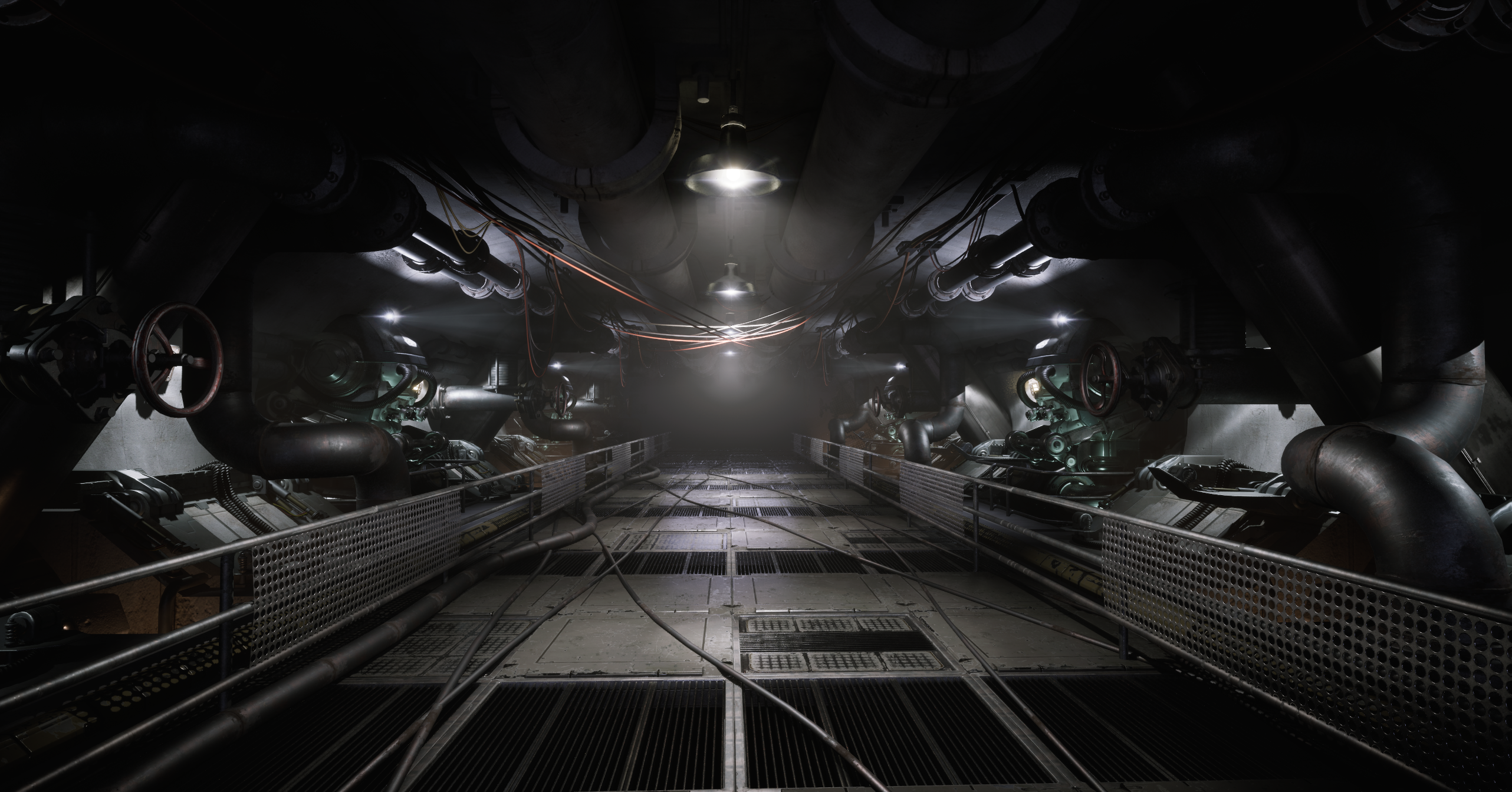


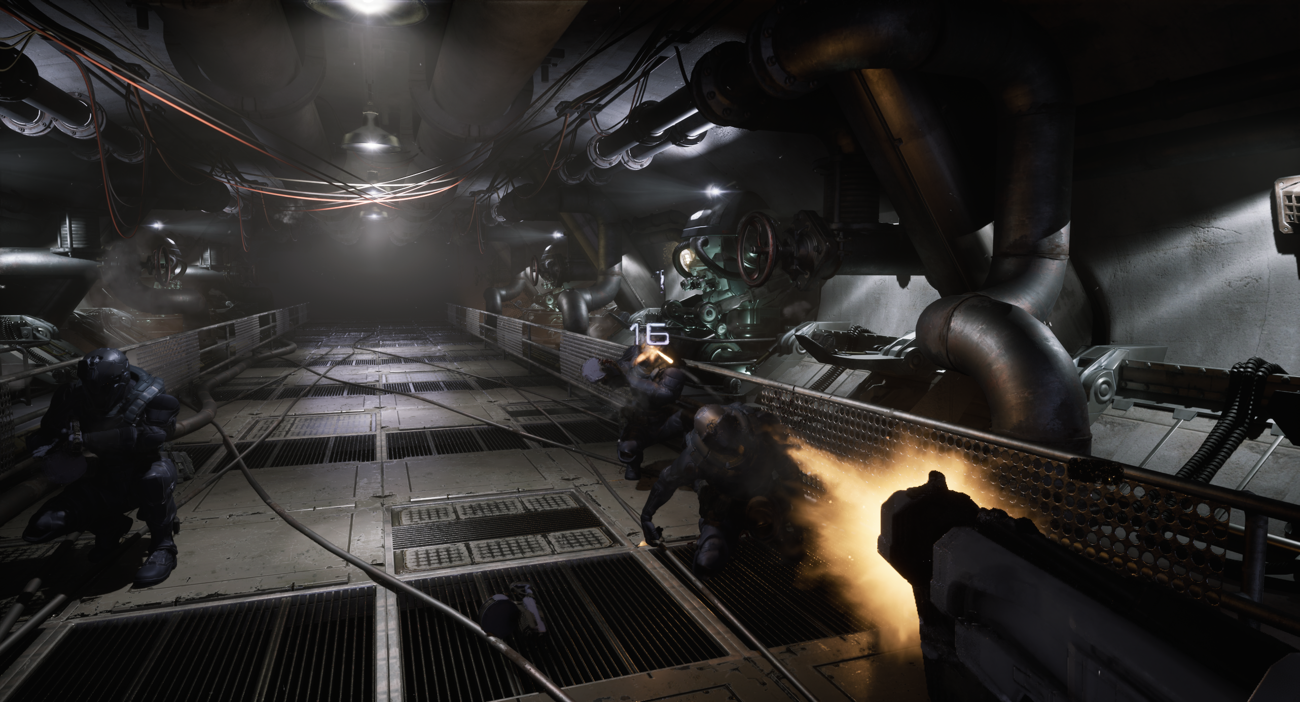
Execution video
- Final Result
- Infiltrator Assets
- Layered Materials
- Why to use PCG?
- My experience with PCG
- PCG – Floor
- PCG – Left Wall
- PCG – Ceiling
- PCG – Ground
- PCG – Learning Materials
- Lighting
- Destroying Lights
- Pipe Steam FX
- Conclusion
Infiltrator Assets
If you’ve read the earlier tutorials, you already know how to migrate assets from one project to another. Since I’m sharing this project with you, I can’t use any paid assets, and I don’t have enough time to create everything from scratch. So once again, I’ll be using assets from the Infiltrator project that Epic shared with us a couple of years ago.
What’s really great nowadays is that we can modify assets directly in the editor using the Modeling Tools. Most of the assets from Infiltrator are modular, but I had to make a few modifications to some of them.
Layered Materials
One important thing to point out is that the Infiltrator project uses a Layered Materials approach. This is something you should definitely analyze and be aware of, as it’s a common and industry-standard technique.
You can read more about it here:
🔗 Layered Materials Overview
The concept behind layered materials is to assign different materials to different surface types, such as:
- Metal
- Rust
- Skin
- Leather
- etc.
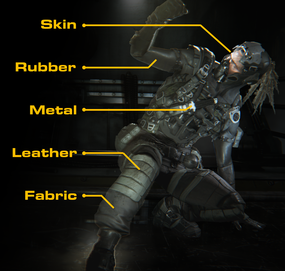
Then, a mask texture is used to define which material should be applied to which part of the mesh.
This Approach Offers Several Benefits:
- Better artistic control:
Artists work with separate layers, which makes workflows more modular and flexible. For example, if you’re outsourcing, you can just send the material layers and expect consistent use. You can also tweak layers globally, ensuring visual consistency across assets. - Easier management:
You maintain a library (or backlog) of reusable layers, which can be updated, iterated on, or swapped out efficiently. - Potential memory savings:
Especially useful for large, open-world or realistic games where you’d otherwise need many unique textures.
However, There Are Some Trade-offs:
- Performance impact:
Since all layers are still rendered, performance depends heavily on shader complexity and how efficiently the layers are used. - Learning curve for artists:
Artists unfamiliar with this method might need to adjust their workflow and thinking.
With Unreal Engine 5, there’s an even newer system for material layering that improves flexibility and usability:
🔗 Material Layers
Why to use PCG?
In my opinion, PCG (Procedural Content Generation) is one of the best tools Epic has introduced for level artists. Sooner or later, you’ll probably end up using it—and here’s why:
- Non-Destructive Workflow
You can iterate during production without needing to recreate everything from scratch. This makes experimenting and improving your levels much faster and less risky. - Modular Mindset
Using PCG changes how you think about building environments. It encourages a modular, procedural approach—which is standard practice in the industry today. - Easier Debugging & Optimization
Too many draw calls? Reduce the number of components in the graph. Too many overlapping lights? Decrease the light spawns or increase their spacing—and everything else will adapt automatically. It’s easy to tweak and test. - Easy to Learn
Compared to tools like Houdini, PCG in Unreal is much more beginner-friendly—especially when you’re just getting started. - Fast & Flexible
PCG is fast. You can even leverage the GPU or drive behaviors using HLSL code, similar to Niagara. It’s built for performance. - Runtime Generation
You can generate content at runtime with no hitches. This is perfect for dynamic details like grass, pebbles, or other small elements that only need to appear near the player. The same goes with hierarchical generation – you can chose density depending on the distance. - It’s still improving and Epic is constantly working on it
Why to use PCG in the Shooter Tutorial?
Because I’ve never done an indoor scene with PCG before—and this is a great opportunity to explore how it performs in more constrained, interior environments.
Another important goal for me is to have the ability to dynamically change the tunnel length and width, so that level art can adapt procedurally to level design. This kind of flexibility is crucial when building gameplay-driven environments, and PCG makes it not only possible but efficient.
My experience with PCG
I’ve worked on many aspects of PCG before, including:
- Runtime GPU-based details, using Niagara GPU systems for visualization instead of HISM
- Custom tools for Level Art, such as roads, fences, buildings, beach lines, and more
- Open-world biome generation, for large-scale environments
However, I haven’t had the chance to explore indoor environments using PCG until now. So please keep that in mind—this will be an example from an intermediate user, not a power user with indoor experience. The PCG graph took me two days to create. I should invest more time into it, but this should serve as just a starting point for you all.
Some day – my goal is to create a 100% procedurally generated dungeon – where each brick is procedurally placed.
PCG – Floor
PCG Parameters
In PCG, there are several ways to create and store parameters, depending on how you want to control and reuse them throughout your graph.
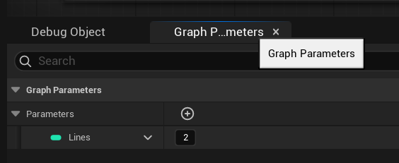
Graph Parameters. These are exposed parameters that can be modified directly in the Details panel of the PCG Component. They’re useful for making your graph flexible and customizable per instance—great for tweaking values without opening the graph itself.
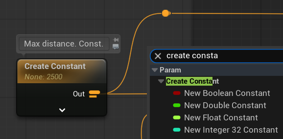
Constants. Constants are parameters defined inside the graph only. They cannot be changed from the outside, making them ideal for values that shouldn’t vary between instances.
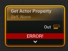
Actor Property. This method allows you to pull values from the owning Actor, such as variables from a Blueprint. It’s especially useful when your PCG system is part of a tool—for example, a road spline tool where the spline shape or size is driven by the Blueprint logic.
I’m creating a point grid that starts from the level center at (0, 0, 0). There are two key parameters involved:
- Lines (int, Graph Parameter)
This controls how many enemy lines the level will have — for example: 1, 2, 3, or 4.
This parameter directly affects the width of the level, with more lines meaning a wider playable area. - MaxDistance (float, Constant Parameter)|
This defines how far the level should extend outward from the center point.
It sets the maximum distance for point generation along the grid and determines the overall length or depth of the level.
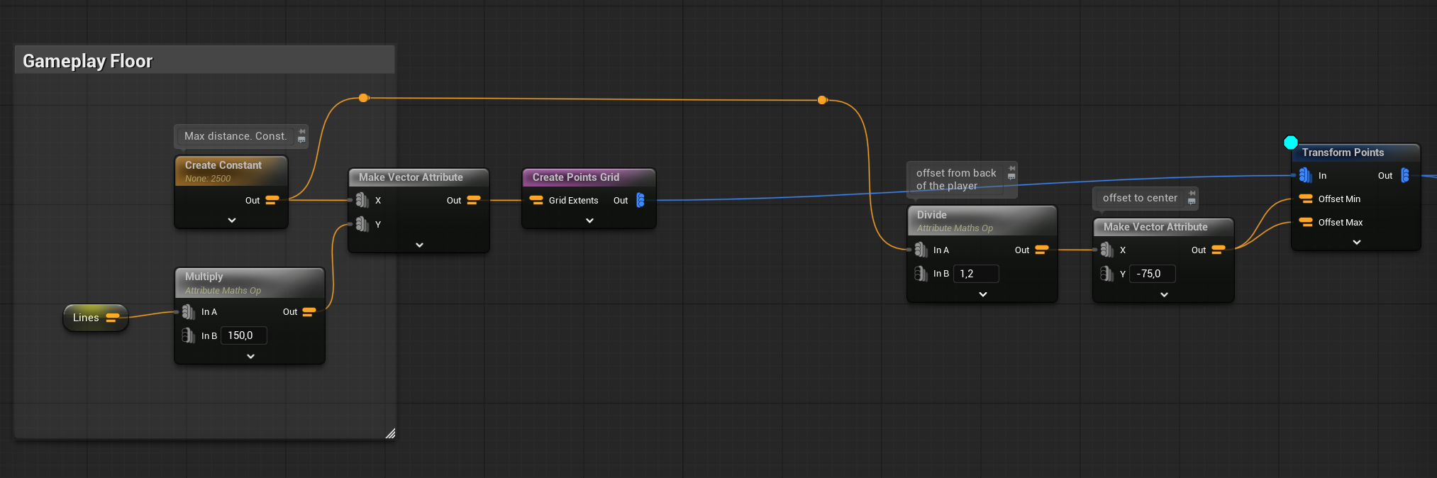
As you can see, I’m offsetting the entire grid so that it aligns properly toward the level center. Additionally, I apply a horizontal offset because my floor tiles have their pivot point in the corner, not the center.
But now, how can I create a non-random pattern for the floor tiles? I have a few different floor meshes, and I’d like to arrange them in a way that doesn’t look random. There is couple of ways of doing it. I will show you the easiest using Modulo.

PCG Custom Execution Blueprints
Let’s take a look at IndexModuloToDensity. What’s cool about PCG is that you can create your own execution nodes, which can perform custom operations on your points.

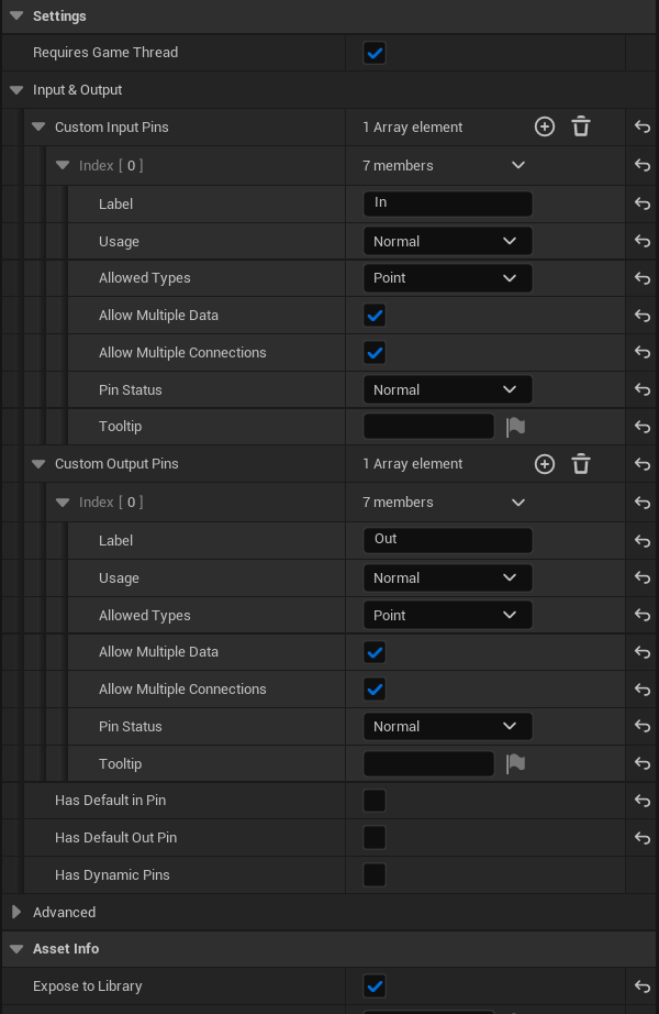
In the details panel, you can define the inputs and outputs. Don’t forget to configure them properly for your Blueprints—it will make using them later in the graph much easier.
Override Execution Function. You have two options for overriding the execution function:
- Execute with Context.
Here, context means the owning Actor, random streams, and basically everything with the input points. This option gives you access to more information during execution. - Execute.
This option runs without context—you only have access to the points provided as input.
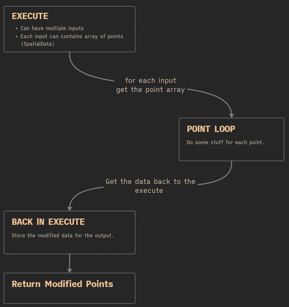
When working inside the execution function, you need to retrieve the data from the input pin somehow.
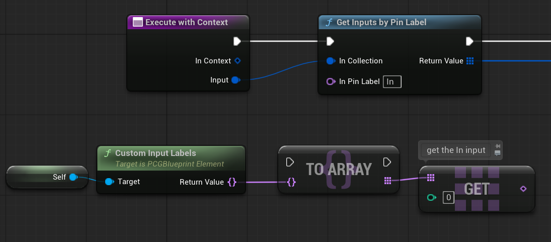
Once we have the input, we need to check what kind of data it contains and then iterate through its contents.
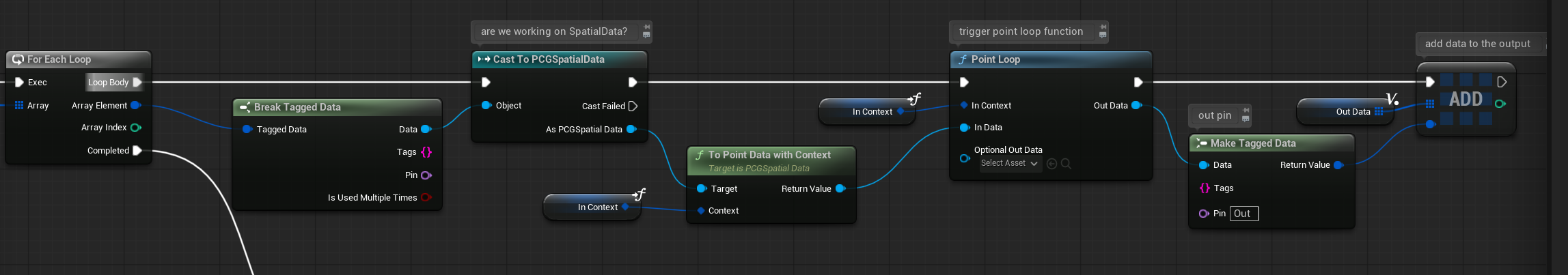
Point data in PCG is of the PCGSpatialData type. This provides an object containing an array of points. For each point, we want to perform some calculations. That’s where the Point Loop function comes in—it allows us to process each point and returns the modified data, which we then output.

Let’s take a closer look at the Point Loop Body function.
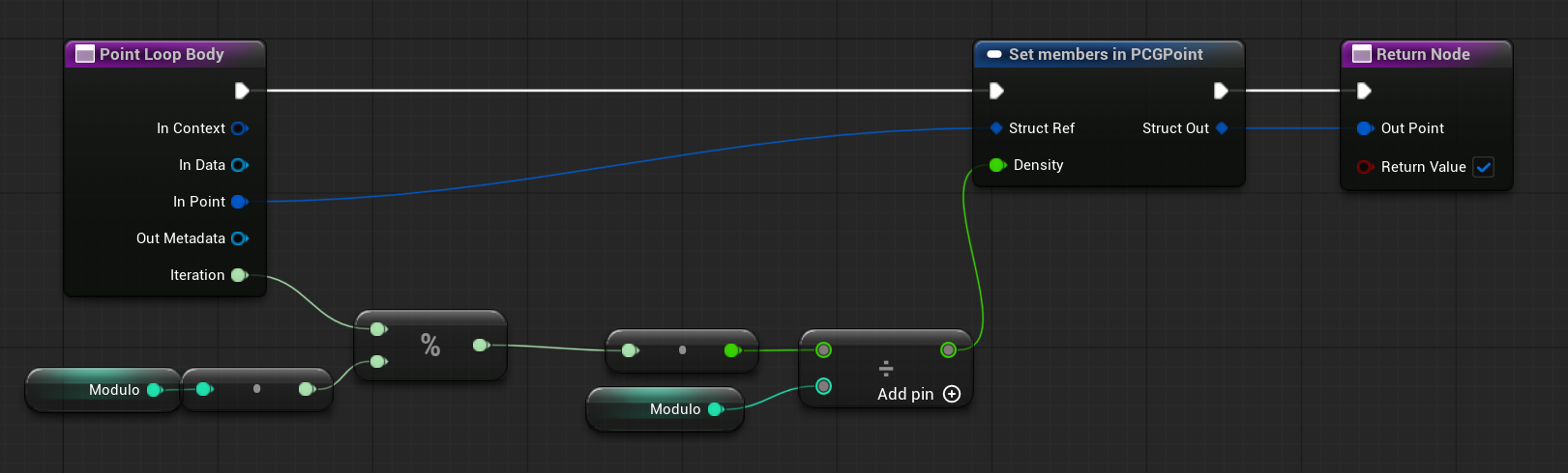
It simply sets the density parameter inside each point based on the modulo of the iteration index. That’s all there is to it.
This is how the loop looks:
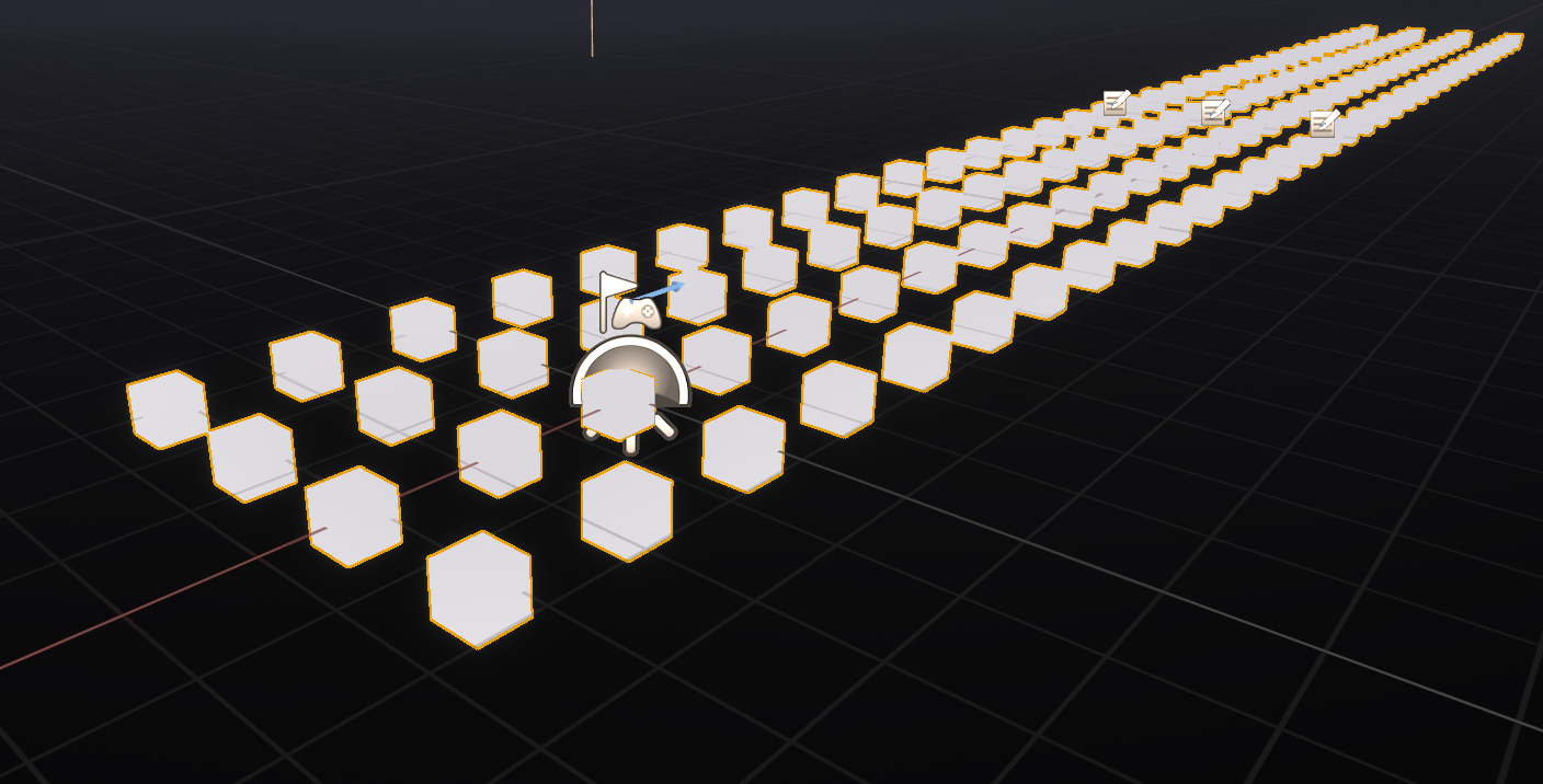
So our points are looking like this now:

You can change the modulo to use different patterns:
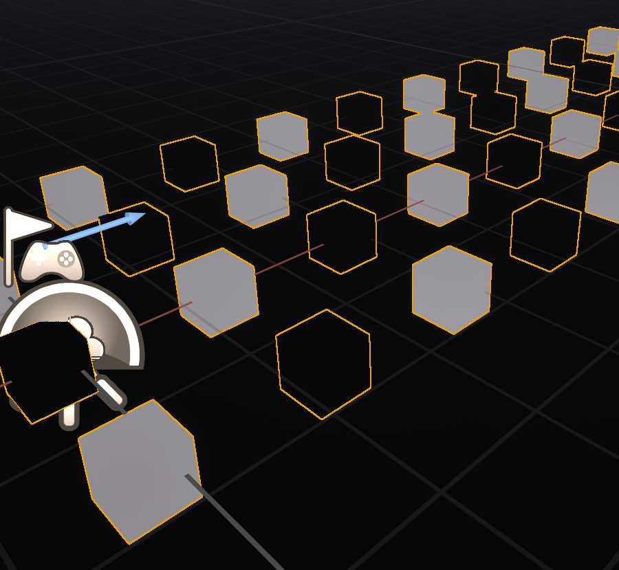
Density Filter or Attribute Filter By Range can be used to determine which mesh should be spawned.
As you can see, I’m also using Index Modulo to Density to add more variety inside the one row of points.
This way, the floor doesn’t look too random. You can spend more time refining the pattern if you want.

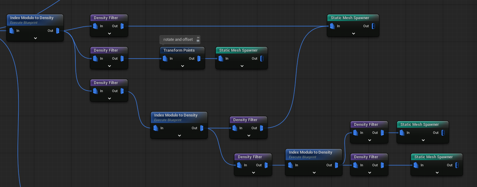
PCG Draw Calls
One very important thing to remember when working with PCG is that each Static Mesh Spawner node creates an ISM/HISM component, which counts as one draw call.
In your graph, you might use the same pipe asset in multiple places—like the ground, ceiling, and walls—and it’s easy to accidentally duplicate the Static Mesh Spawner node for it.

To optimize performance, you should always use one Static Mesh Spawner per mesh. This helps reduce draw calls to a minimum.
I deliberately left some duplicates in the graph as an example, hope you can find them 😉
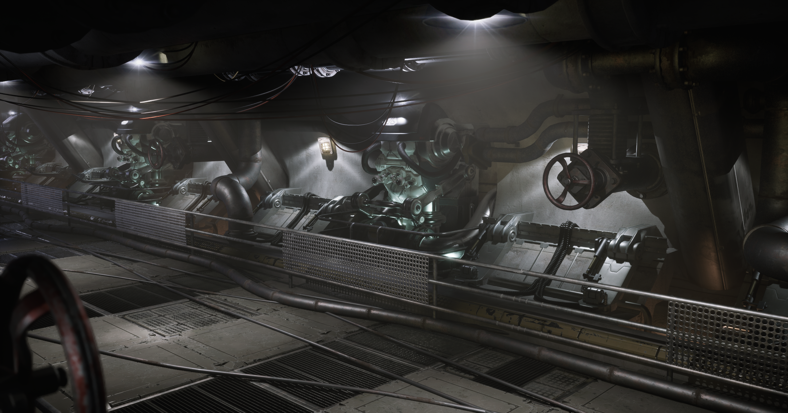
PCG – Left Wall
Now that the ground is set up properly, it’s time to move on to the walls. I’ll start with the left wall, since the right wall will simply be a mirrored copy of it.
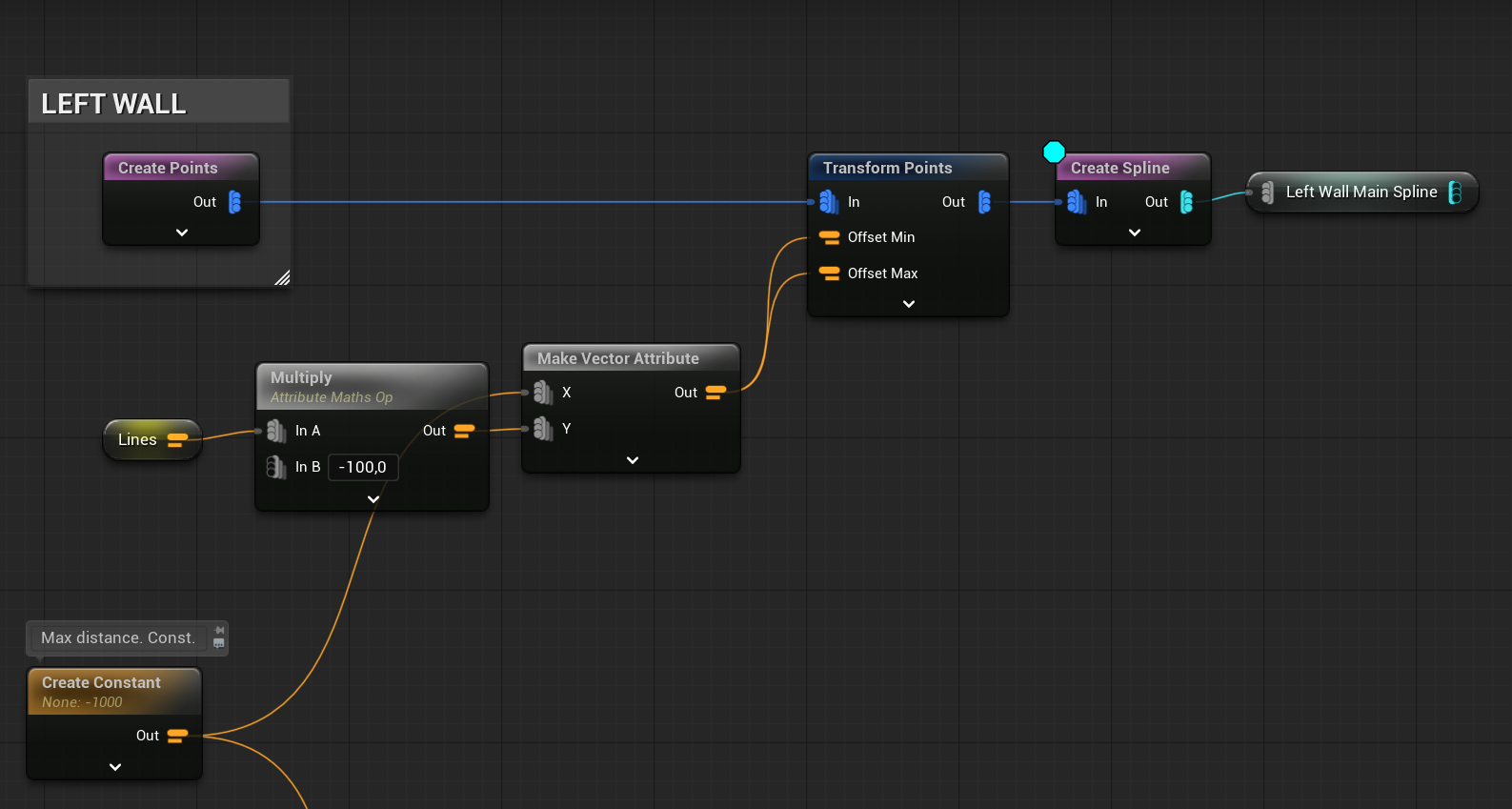
The base is just a start and end point. It shifts to the left as the Lines value increases.
At this stage, we’re using those points to sample along a spline, which helps define the wall’s shape or placement.

I’m using the same points, applying slight offsets, to place the pillars alongside the wall.

Lights – Spawning Actors
In PCG, you can also spawn actors, and I’m using this feature for my lights. This allows me to light up the level and have full control over the lighting setup.
I plan to add small lights at the base of the pillars, but only near the center of the level. The Distance to Density node is really handy for this—it lets you control where actors spawn based on their distance from a specific point.

PCG Data Assets
One of the most important parts of PCG is the use of PCG Data Assets. These assets act as prefabs, storing a collection of meshes or actors that can be tagged and referenced within your PCG graphs.
In my case, I’ve created a data asset called WallsPipes_c, which contains the level elements for walls and pipes.

Each pipe has a SteamFX tag, which will later be used to spawn steam effects—I’ll explain that part later.

💡 Note: You can tag actors, and when the PCG graph loads a PCG Data Asset, it will include those tags as part of the data inside the graph. This allows you to filter, sort, or trigger logic based on tags.
To create a PCG Data Asset, simply use Create PCG Asset from Level.

💡 Note: Keep in mind that if you make any changes to the level, you’ll need to recreate the PCG Data Asset to update it.

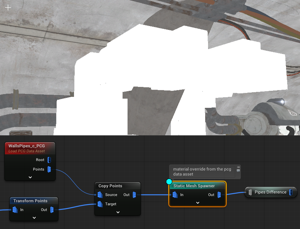
Now, in the graph, we can use these Data Assets along with all the points they contain.


Each point from the Data Asset includes additional information, such as Material and Mesh soft references.
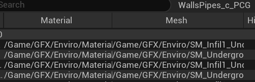

The Static Mesh Spawner uses this data to spawn the components. This represents a different approach to the logic used by the Static Mesh Spawner. What’s great is that you can create your own custom logic to control how the components are generated.
I’m using the same spline sampler with some offsets to add Tech meshes to the wall.

Using the same points with offsets and the Distance to Density node from earlier, I’m also adding additional lights.


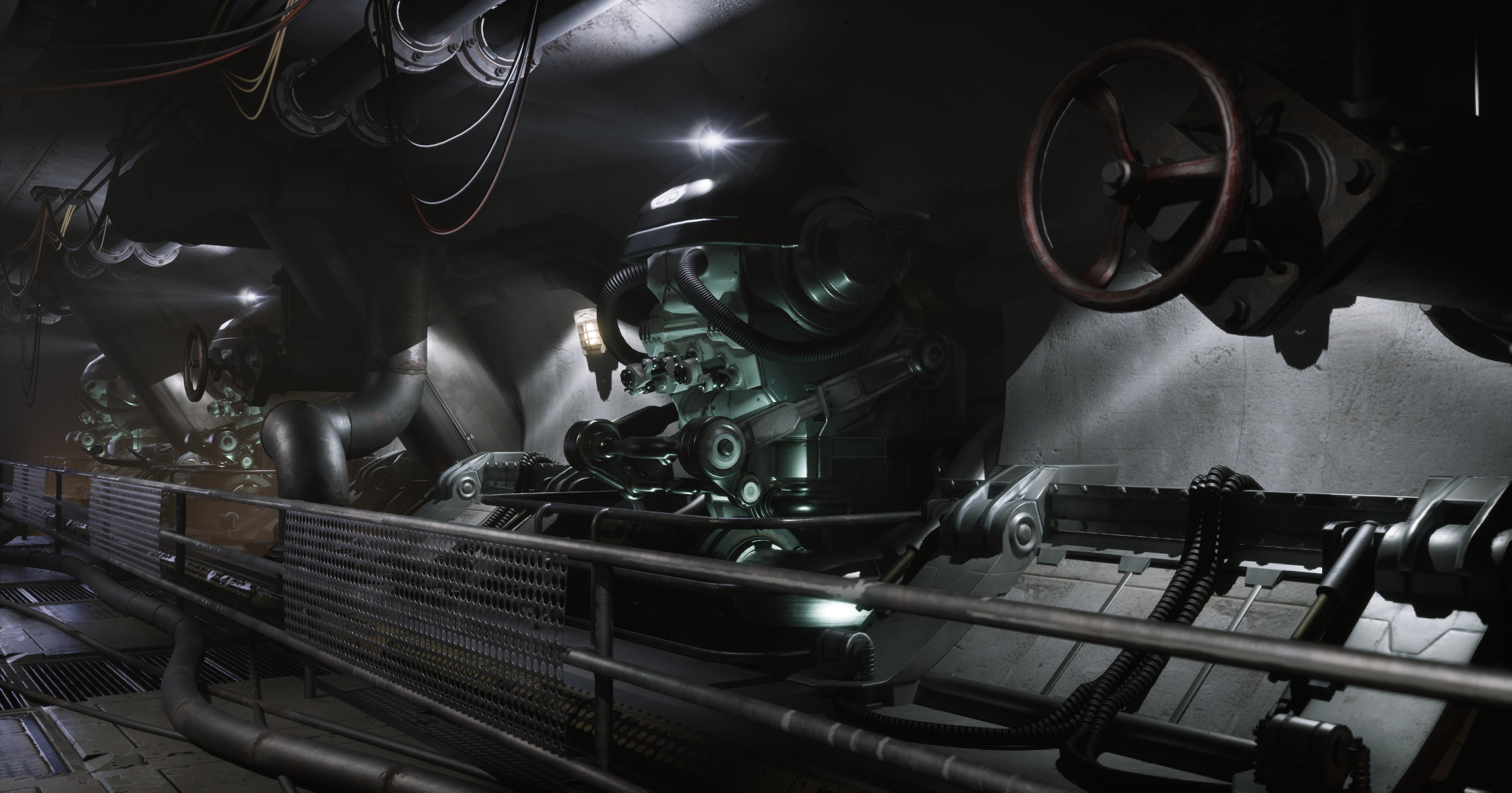
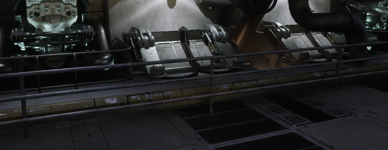
Using another PCG Data Asset, I’m adding robot assemblies to the wall.

And I’m adding lights to the robots using the same method as earlier.

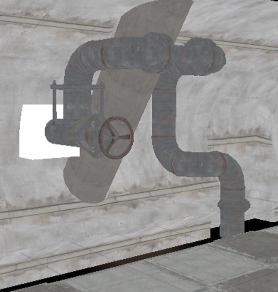
The wall pipes are also PCG Data assets which just to be properly placed.

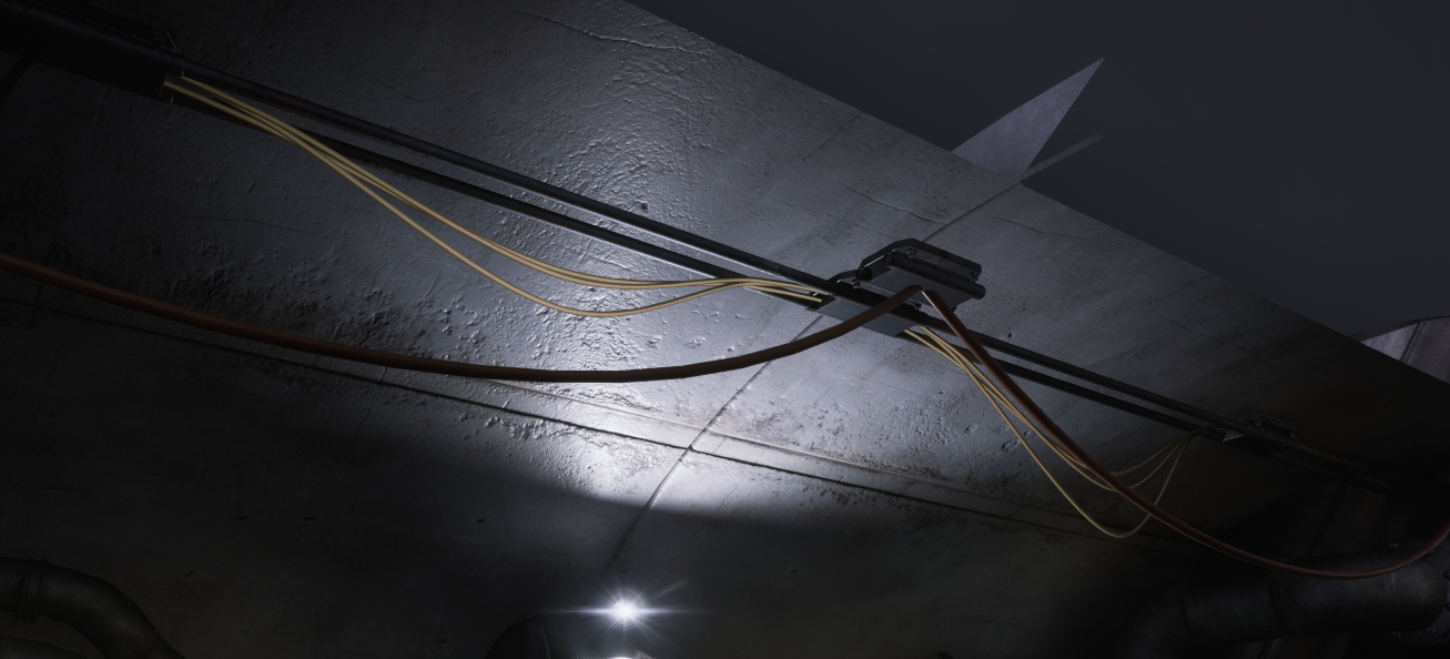
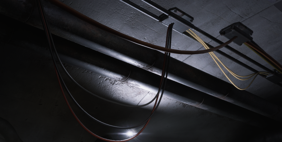
Using the same wall points but with different spline sampling, I’m adding wires.
Difference Node

Here you can see that the wire is intersecting with the pipes.
When creating the pipes, I saved their output.
Before spawning the wires I have changed their bounds to be bigger.

This way, I can use the Difference node to check if the wire bounds intersect with the pipes.
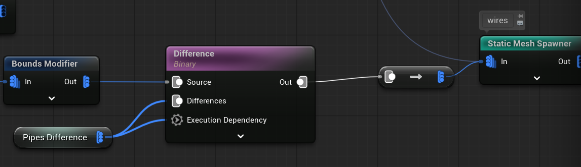
You’ll use this node a lot, but sometimes it might not work as expected—mostly due to the order in which operations are executed.
💡 Note: I’s important to use Execution Dependency. This ensures the node waits until the pipe points are fully generated before running.
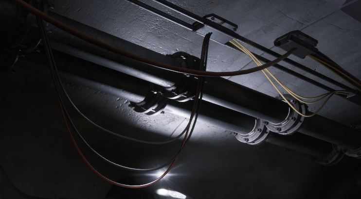
Using the same base points, I’m adding additional pipes to the wall—this time without using PCG Assets.
And caps:
Using the same left wall base points with some offsets and modulo density, I’m placing the wall floor.


And railing
With some detail

And walls are ready with using really simple logic:
- SplineSampler,
- TransformPoints
- Index Modulo to Density (our custom node)
- Distance To Density
- Density Filter
- Bounds Modifier
- Load PCG Data Asset
- Copy Points
- Static Mesh Spawner
- Spawn Actor
- Difference
So just by learning those nodes you can layout your levels procedurally.
PCG – Ceiling
By using the floor points I’m offseting them and creating the ceiling. Normally I would create different meshes with different grid for ceiling, but I haven’t had any good examples to use in Infiltrator.

I also have start and end points for the ceiling (similar to the walls), which I can use to add some meshes.

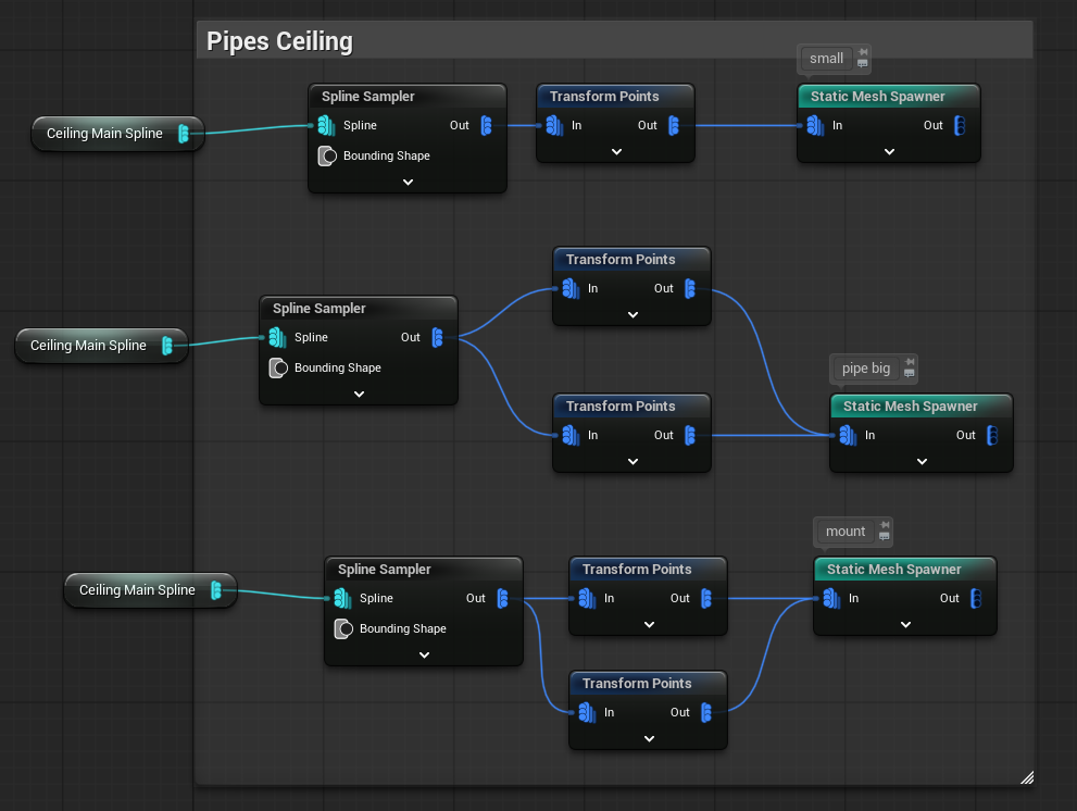
Using the same method for placing light actors, I’m adding ceiling lights.

Ceiling Wires
I want to create wires that hang from the left side of the tunnel to the right. And I have points on both sides.

Now how to:
- Randomly choose one point on the left side and one on the right side of the tunnel.
- Use the selected points to create a spline mesh, which will act as the wire between them.
I have created Execute Blueprint to do that.

Let’s take a look at the LeftRightBridge Blueprint. Keep in mind, this is a prototype, and it still needs some polishing. Here are a few improvements you could make:
- Use the Execute with Context function to enable proper seed-based randomness.
- Replace the three separate nodes with a For Loop node, so you can control the number of iterations dynamically.
- Improve the point selection logic to ensure the points aren’t too far apart and don’t reuse the same ones.
- Implement a better tangent attribute, which can be exposed as a configurable parameter directly in the Blueprint.
I haven’t implemented these improvements because I’d like you to try them yourselves—consider it a bit of homework 😉
Let’s take a look at the node defaults—we’re using two inputs: Left and Right, and two outputs: Left and Right.

We’re currently using only the Execute function, which means the random values aren’t consistent—every time you change something in the graph, the node gets regenerated with different results.
To fix this, you should use Execute with Context and retrieve the random stream from the seed. This ensures stable and repeatable randomization.
| OutData | PCGTaggedData Array | This holds the data that will be returned. It contains the points for the Left and Right outputs. |
| PCGPointArray | PCGPoint Array | This will hold the actual selected points. |
Here’s the Execute blueprint.

And GetRandomPoint custom function

Yes, it’s that simple.
- Get one random point from the left side,
- Get one random point from the right side,
- Output them,
Just make sure to use the Merge Point node afterward so the data can be used properly by the Create Spline node. And yes—you can create spline mesh components directly in the PCG graph!
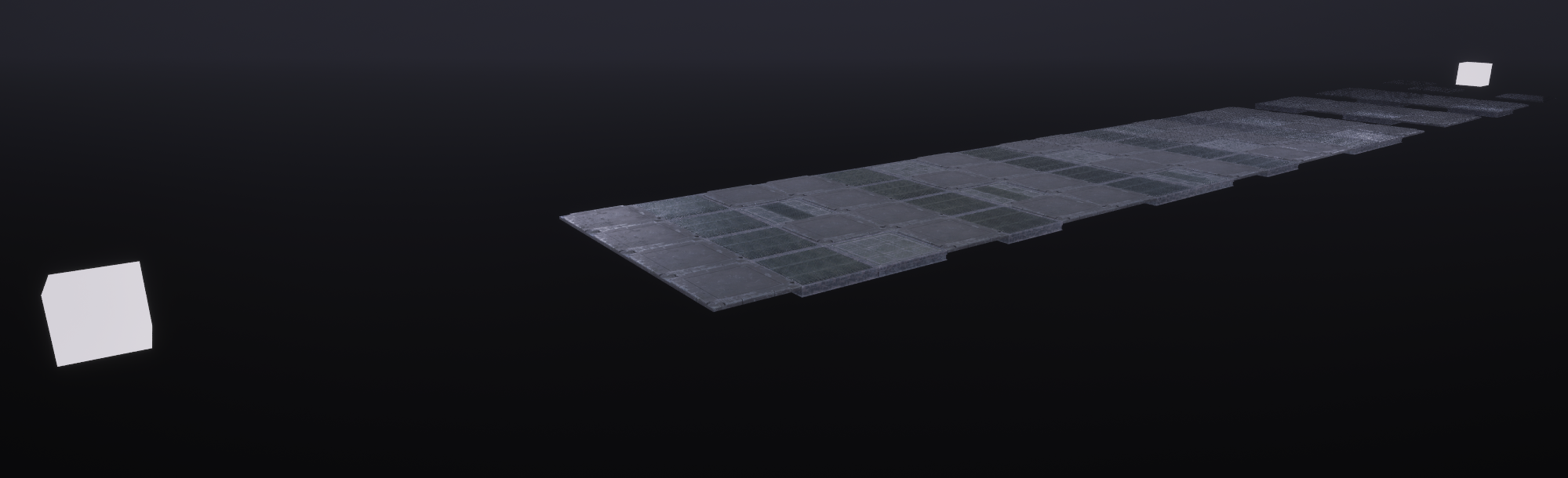
PCG – Ground
I created a long spline mesh to demonstrate how you can build more complex procedural splines.
In this particular example, it’s not ideal to use a spline mesh for something as simple as a single pipe lying on the ground —it would be more efficient to use a static mesh instead. Using spline mesh components in such cases can be unnecessary overhead.
But—this is still a valuable example to show how you can modify points to generate procedural spline meshes.
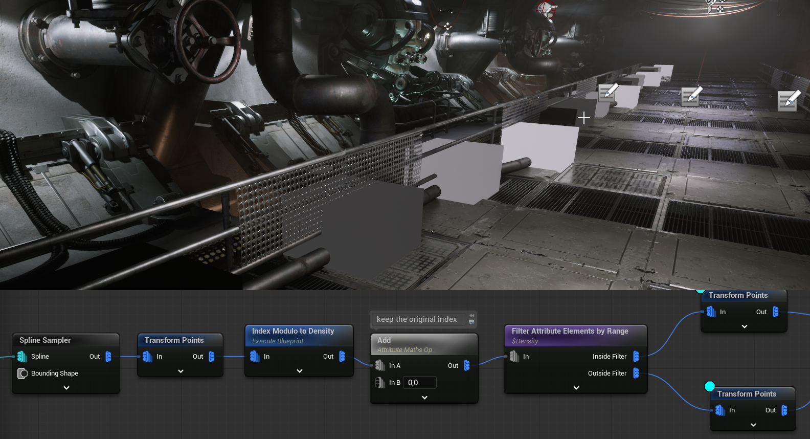
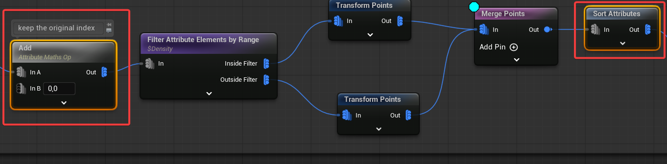
As you can see, the white point uses an offset, which could simulate a collision or deviation from a flat surface. This results in two separate PCG Spatial Data sets. However, the Create Spline node requires a single spatial data input with correctly ordered points.
That’s why, before splitting the spatial data, I saved the original index. Then, after merging the data back together, I used this saved attribute to reorder the points, ensuring they have valid indices for the spline creation.
After generating the spline data, I sample it again to gain better control over the density of the final spline.
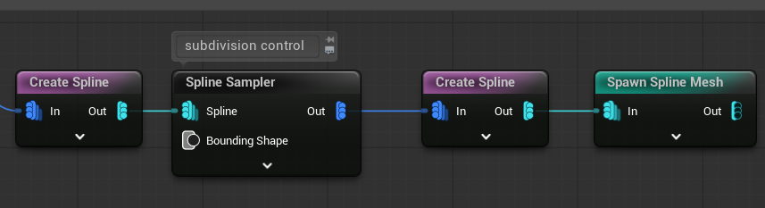
The result is a procedurally created spline mesh pipe, generated entirely within the PCG graph.
Why am I showing you this ? Because this technique can be extended further—you can apply custom point logic (like pathfinding or rules-based placement) to create dynamic spline meshes procedurally.
Ground Wires
The last part covers the ground wires. I wanted to add more detail to the ground using runtime generation, but I wasn’t able to find anything that really fit the overall look of the scene. If I come up with something that works, I’ll extend this tutorial in the future.
Created a floor grid – this defines the base layout for wire placement.

Used the Self Pruning node – this removes overlapping points to avoid clutter.

Added some random offsets to the remaining points – and used those to spawn the wires.

If you happen to find any ground detail assets that Epic has shared with us, which I could use for runtime generation, please let me know!
Here you can find whole execution flow.

PCG – Learning Materials
In my opinion, the best place to learn PCG right now is Adrien Logut’s YouTube channel. He is one of the creators of PCG, and his knowledge is pure gold.
Also #pcg-framework channel in Unreal Source Discord server can be helpful.
Lighting
I’ll cover the lighting setup in a separate post where I’ll go into more detail, but here are a few quick notes:
- Auto Exposure is disabled in the project settings.
- The fog is volumetric.
- The environment uses a distance fade shader called
MF_GlobalDitherFade. - Reflections in the environment are disabled based on distance. (check the base materials)
- PCG assets use cull distances to optimize rendering.
- Lights have a maximum draw distance set.
- The level’s post-process settings include Lumen Sky Light Leaking adjustments.
The Shooter Tutorial should have a distance black fog effect, which was easy to create in UE4. However, in UE5 it’s more challenging due to Lumen, reflections, and lighting. I’ll explain this in more detail in the next post.
Destroying Lights
Each light in the game can be destroyed by the player, thanks to the modular damage system we set up earlier. This is easy to implement by:
- Implementing the IDamage interface on the light actor,
- Overriding the ReceiveDamage function,
Which allows the actor to handle damage independently.

Pipe Steam FX

I wanted to create a custom effect when a bullet hits a pipe. Since our level is spawned procedurally with PCG, we need a way to mark the pipe components.
Simple method: Add a SteamFX tag directly to the component.
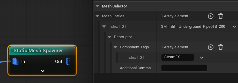
But what If we are using PCG Data Assets?

Here, we can use Property Overrides. This feature searches for a property by name (for example, bOverrideLightMapRes) and sets its value based on the selected point data (in this case, SteamFX).
I chose to use bOverrideLightMapRes because it’s a boolean property exposed to Blueprints in the Mesh Component.
If you want, you could create your own custom ISM Descriptor to pass data to a custom ISM Component (custom bool named bIsPipe) class, allowing more control over the behavior.
💡 Note: This is a situation where modifying the base engine could be really helpful, as it would allow you to add custom tags to components based directly on point data.
Now, in the Weapon::SpawnHitEffects function, we need to inform the audio-visual manager that the bullet has hit something, because we might later add more features, such as steam effects similar to SteamFX.


Later on I will improve the pipe steam to track which pipe was damaged.
Conclusion
I believe that with a few more days of work on the PCG graph, I could have created a large, fully generated level with rooms, tunnels, and more. I genuinely enjoy procedural generation.
But this isn’t just about me—it’s about you. Seriously, give PCG a try. Start small. Learn how it works and experiment with integrating it into your own projects.
That said, it’s time to move forward with the Shooter Tutorial. Next time, we’ll focus on Lighting.

You must be logged in to post a comment.